Victron with Pylontech Batteries


This document is intended as a starting point for understanding the various connections required to build and commission a solar/battery power system using Victron components and specifically with Pylontech batteries. Please refer to the product manuals for specifics on installation requirements and advice. Illustrations throughout show the various connection points of the products and what they are used for as well as example wiring diagrams.
For grid-tied ESS systems, the Victron ESS design and installation guide can have a lot of useful information not covered here.
Victron also has an integration guide for their products with Pylontech batteries which covers all settings for different products and applications as well as an FAQ.
Battery Power Connections
Data Connections
Configuring the Multiplus/Quattro inverter/chargers
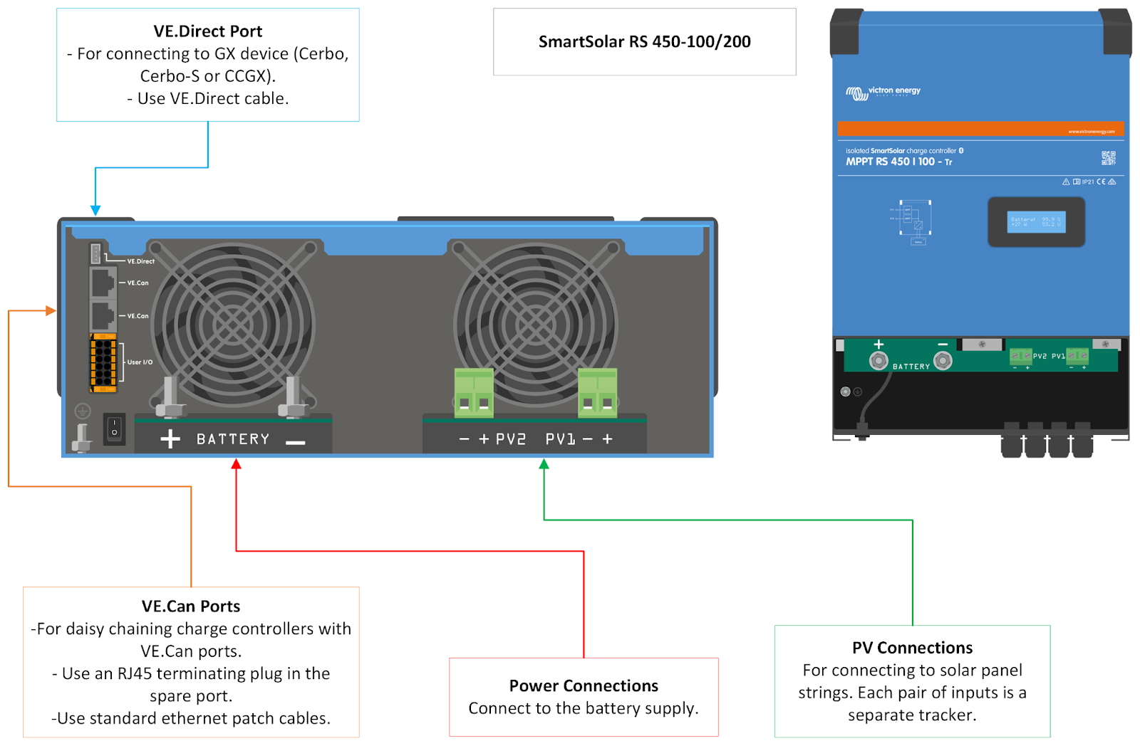
Configuring the SmartSolar
Commissioning and First Start Up
Configuring the GX Device
Setting up the System on the VRM Portal
Midsummer Energy will not take any responsibility for incorrect wiring or installations. All products and systems are intended for installation by a competent person, ideally a qualified electrician.
Battery Power Connections
Please make sure that all polarities are observed on the AC and DC wiring. Failure to do so will damage products and is not covered under the Victron warranty.
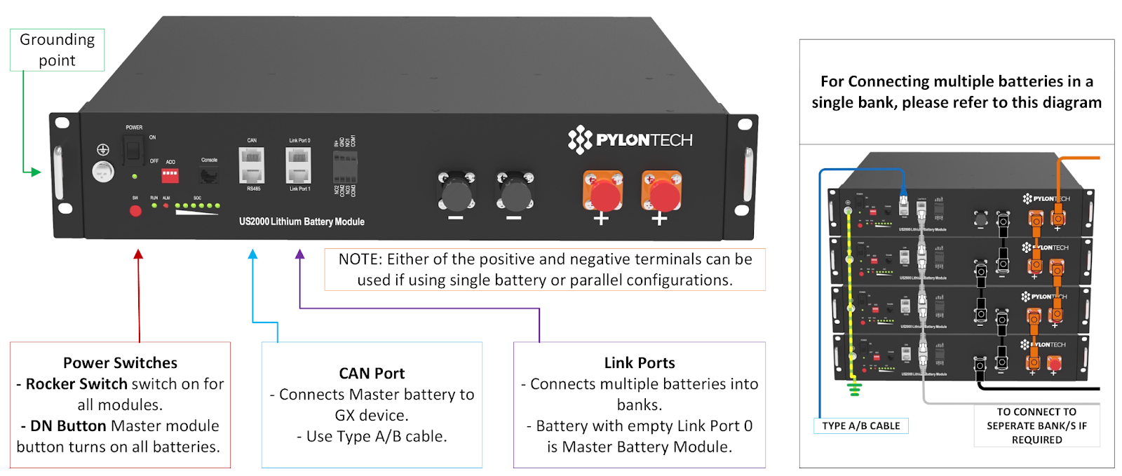
Connect the modules of the battery bank together as illustrated in the Pylontech wiring guide below. Please refer to the Pylontech manual for further information on using stacking brackets, enclosed 19” cabinets, earthing and operating environment. Power link and Data link cables are provided with each module.
Use the Pylontech 2m orange/black pre-terminated cables to connect the Pylontech battery stack to the Lynx Power In/Distributor busbars if they are being used, enclosing suitable MEGA fuses in the Distributor. Do not exceed 125A per set of cables. Connect the cable packs diagonally across the parallel battery stack, or use multiple cable packs at the top and bottom of a stack. When using multiple modules, consider using one cable pack per pair of modules to minimise voltage drop and cell balancing issues.
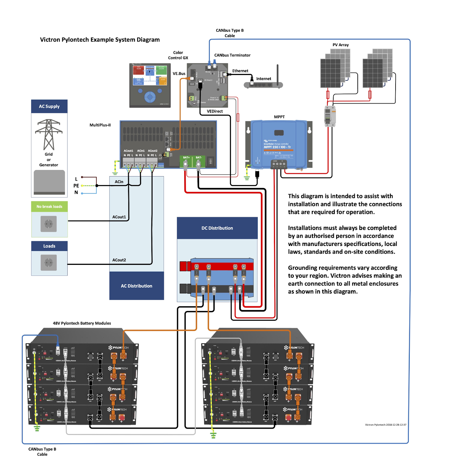
Connect SmartSolar charge controllers, Multiplus/Quattro inverter/chargers and other products to the Lynx busbars in the same manner using appropriate fuses and cable. The GX device (CCGX/Cerbo GX) will require a power supply from the Lynx busbars too. A ready made fused lead is provided with the GX products and can be fed from the positive terminal inside the Lynx busbars (no additional fusing needed).
Data Connections
The data connections are best illustrated on the wiring diagram above. Please check these illustrations to confirm which cables connect to which ports.
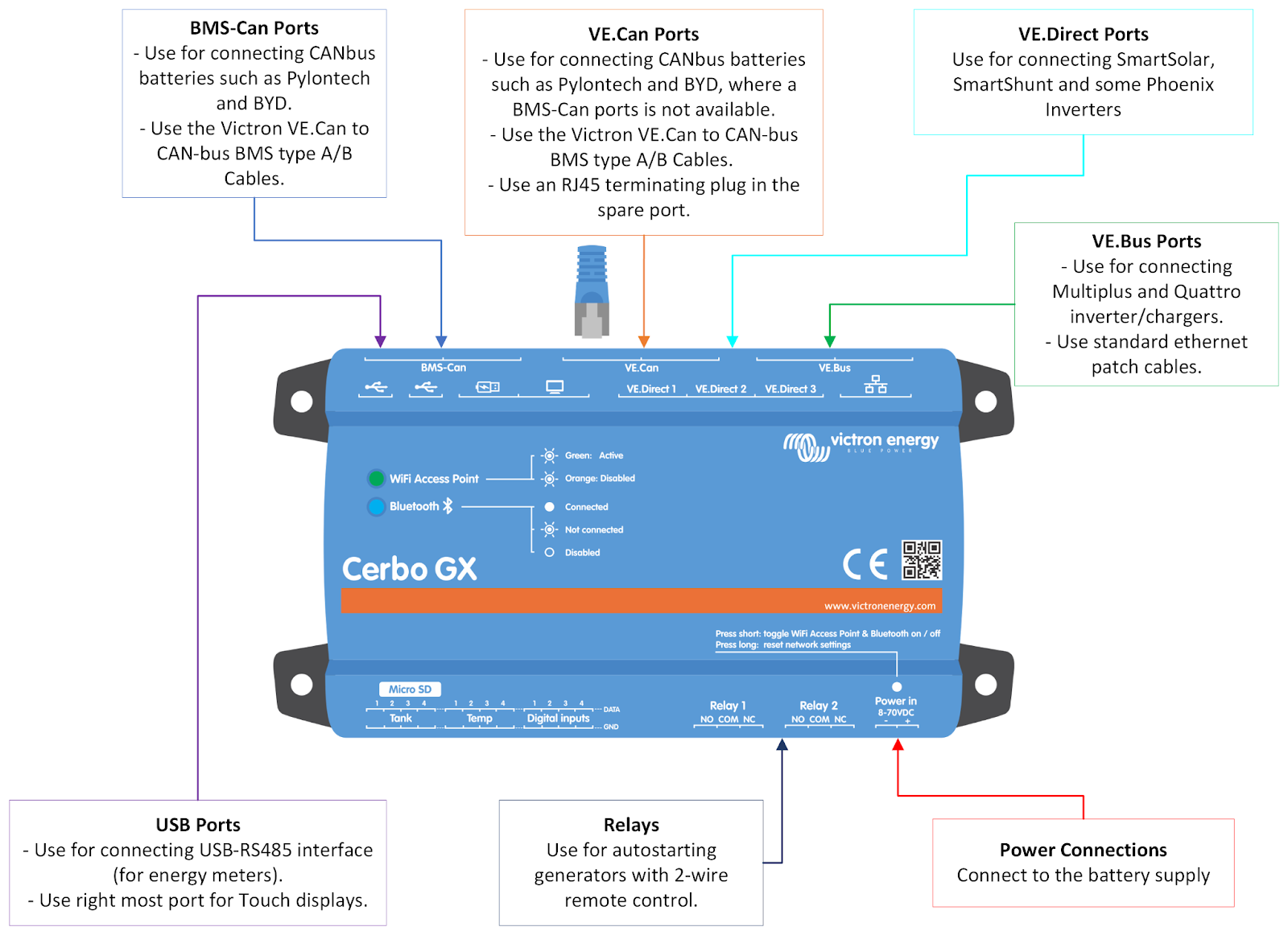
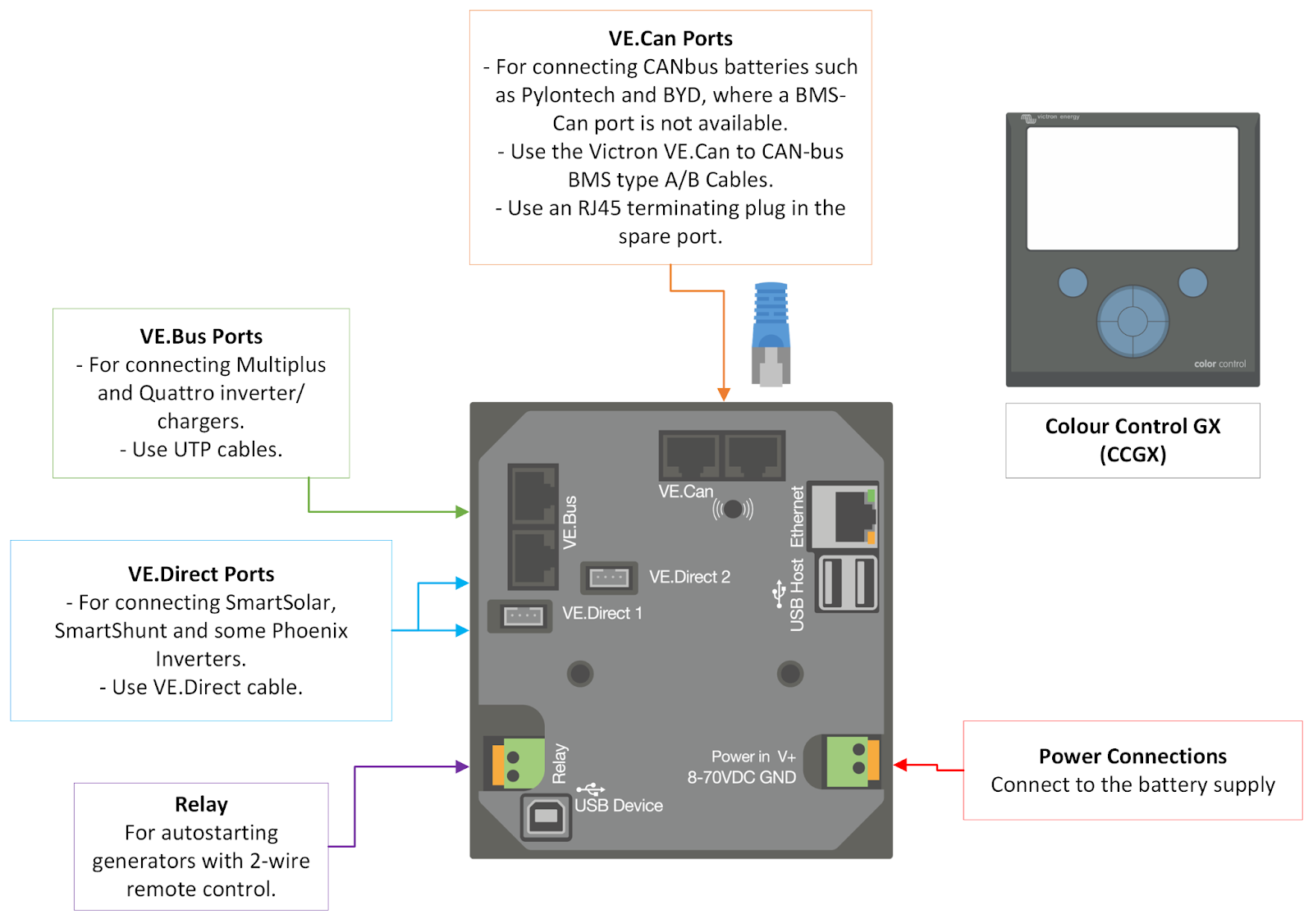
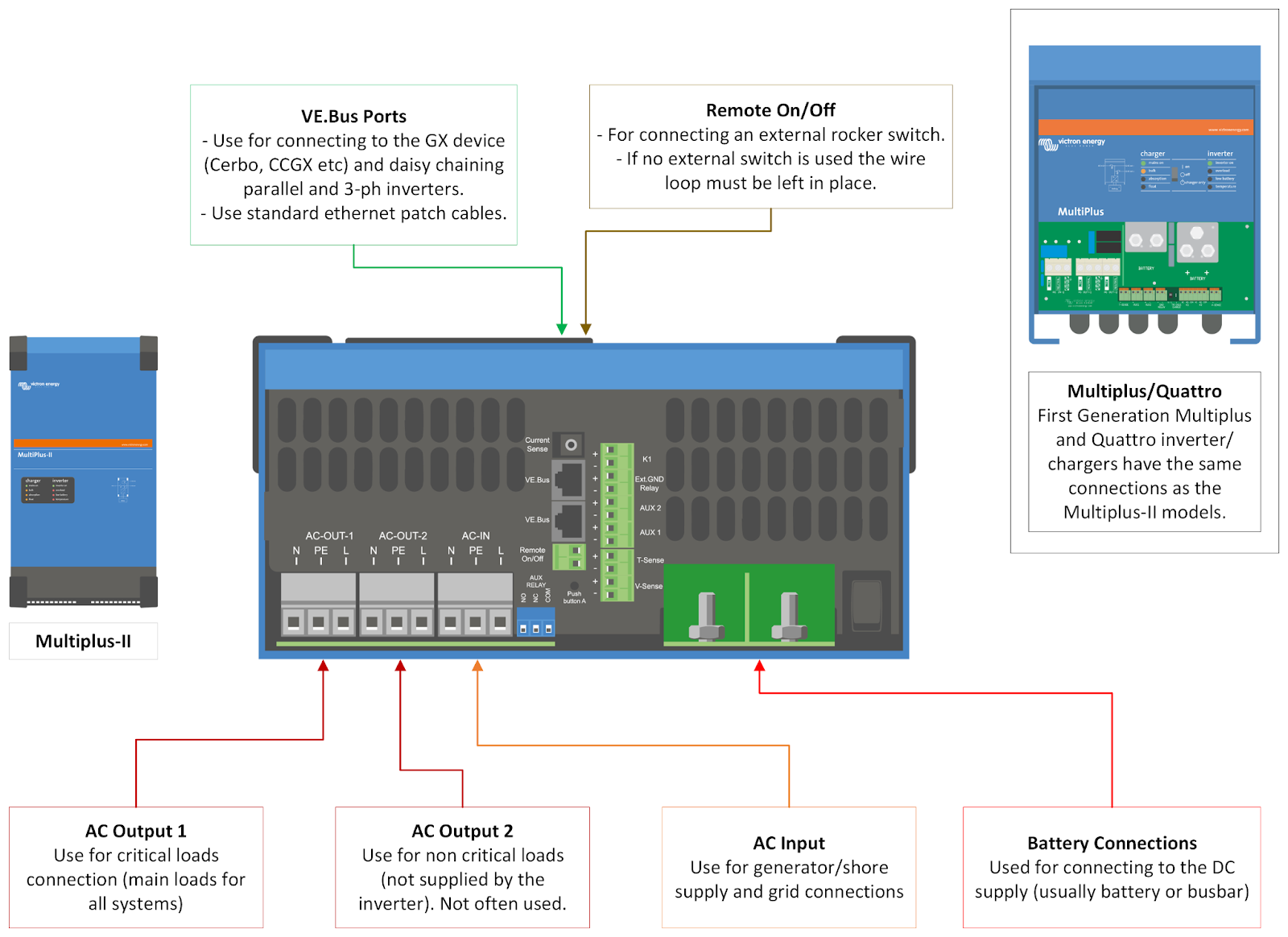
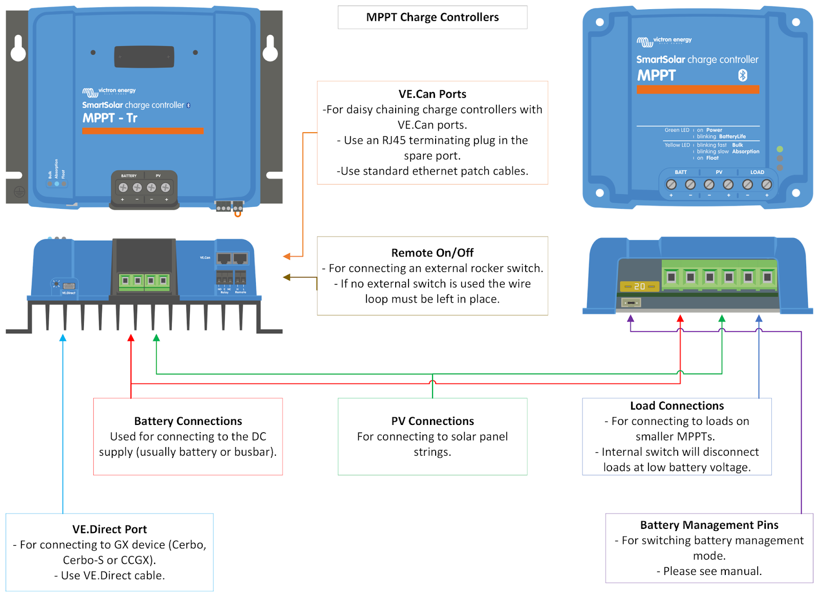
Check the wiring illustrations in this guide to determine the data cable communication between the various products. VE.Bus connections are for the Multiplus/Quattro inverter/chargers using straight RJ45 (ethernet) cables. VE.CAN is used for some SmartSolar charge controllers, particularly when several are installed in a system in a daisy chain fashion; this also uses straight RJ45 (ethernet) cables, with an RJ45 termination cap in the spare port (unnecessary for other cables connections). VE.Direct is used for most SmartSolar charge controllers as well as some other peripherals and uses a bespoke 4-pin cable.
If using the Cerbo GX with the Touch 50/70 display, use the HDMI port and the nearest USB port for power.
The battery communication is provided through a CANbus cable (usually the VE.CAN to BMS CAN Type-A cable) between the A/CAN port on the Master Pylontech battery and the BMS CAN port on the Cerbo GX, or the VE.CAN port on the Cerbo-S GX and CCGX. When using the VE.CAN port, an RJ45 termination plug must be used in the spare VE.CAN port (these come in the packaging for the GX product). This plug is not needed for BMS CAN or any other protocols.
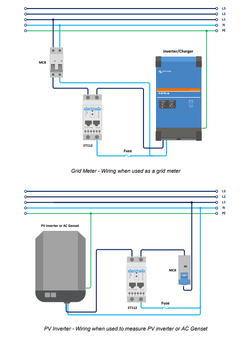
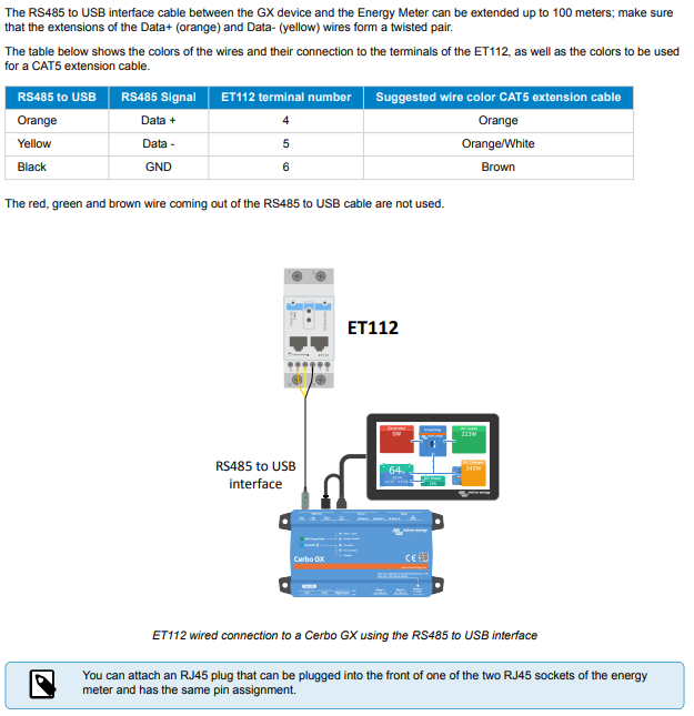
The energy meters, such as the ET112, use a USB-RS485 cable between the meter and the GX device. The AC and Data wiring of the meters can be found in their individual manuals online. A basic overview is in this document. Please see the online Victron manuals for other meters, such as the ET340, Carlo Gavazzi EM24 and EM530 (CT clamp meters) and ABB meters.
Connect the GX device to the internet via WiFi or ethernet (recommended). This is important for remote support and monitoring.
Two wire generator autostart is possible by using the GX device relays, if applicable.
Configuring the Multiplus/Quattro inverter/chargers
The Multiplus and Quattro inverter/chargers can be firmware updated and configured using the Victron Connect software, available on all platforms from Victron’s website and the various app stores. More advanced parameters (such as ESS for grid-tied systems and parallel/3-ph operation) requires the use of a Windows only software bundle called VEconfiguration Tools, including VEFlash and VEConfigure 3, also available from Victron’s website. A USB-MK3 interface (USB-VE.Bus) is required for connecting to these products.
The Victron Connect manual can also be found on their website and software can be downloaded here.
Please read the Victron/Pylon integration guide mentioned above for more details on setting up the ESS assistant settings and other Pylontech parameters for the Multiplus/Quattro inverter/chargers.
.png)
Configuring the SmartSolar
SmartSolar charge controllers can be configured using the Victron Connect software (see above for software links or check the app store) and can wirelessly communicate with the products using bluetooth. This is best done on Android or iOS smartphones.
Make sure bluetooth is enabled, as well as location services, on your mobile device and load up the Victron Connect app whilst in range of a battery powered SmartSolar. It should appear in the Local tab. The default pin is 000000. The product may prompt for as many as two successive firmware updates. Once these are complete, the product is ready to be configured.
The gear icon in the top right of the app accesses the Battery parameters menu. This is where you must set the relevant charge voltages. Normally the type of battery must be selected (lithium in this case) and the Float and Absorption voltages set.
It is best to select the lithium preset option (Victron LiFePO4) and then manually adjust the Float/Absorption voltages to be correct for Pylontech. Float voltage can be set to 51V and Absorption to 52V. Reduce the Absorption period to 1 hour. Nothing else should require changing.
Commissioning and First Start Up
Once the DC system is wired up, the batteries can be powered on. Keep all isolators and equipment switched off. First turn on all battery module rocker switches. Pressing the Red SW button on the Master module (first in the stack, connected to the GX device using the CANbus cable) should light up all the modules in sequence briefly before they turn off again. The Run LED should remain flashing on each module.
Battery isolators can now be switched on and the various products powered up if they have their own switches, such as the inverter/chargers and larger charge controllers. Initially leave any AC or Solar PV connections isolated or disconnected until the correct programming is done, to prevent charging or discharging the batteries incorrectly.
If any products have not been correctly configured, they should be done so now before any charging or discharging of the batteries takes place. See the section of this document regarding configuring the products before proceeding to completion.
Once configuration is complete, AC and Solar PV connections can be completed or deisolated. Avoiding discharging the batteries until they have been fully charged, which can take several hours. This can be done by leaving AC loads disconnected, or the inverter switched off (and other loads isolated) so only a solar charge controller is left to charge them. Or set the inverter/charger to charger only mode (or software equivalent) to charge off the grid or generator supply. This is intended to prevent balancing issues with partially charged modules (new modules ship at ~50% SoC).
Configuring the GX Device
The Cerbo GX manual provides further information on how to use the product. Victron also provide a similar guide to using the CCGX.
A firmware update is normally needed before further configuration. This can be accomplished by connecting the GX device to a WiFi or ethernet connection and finding the Firmware menu under Settings. Change the default option to “Check and Update” for automatic future updates.
Enable ‘Two Way Communication’ in the VRM Online Portal menu, make sure ‘Enable on VRM’ is ticked under the Remote Console menu and also disable the password check for ease of access. Finally enable ‘Remote Support’ in the General menu and reboot to enact changes.
It is important to set the correct BAUD rate for the Pylontech battery communication. This can be accessed in the GX device Settings menu and scrolling down to the Services menu. The 500kbps CANbus option is correct.
Under the System Setup menu, the AC input (1) should be selected (Grid, Shore or Generator) and the battery monitor set to Pylontech.
When using the ESS assistant loaded into the Multiplus, it is possible to set up scheduled charges under the ESS menu.
Setting up the System on the VRM Portal
Register an account on the Victron VRM Portal. Make a note of the VRM Portal ID of the GX device (printed on the white sticker, or available in the settings>VRM Portal menu) and add this ID as an installation on your VRM account. The first to add this installation becomes the administrator and can grant access to other users.
On the Victron website you can register the VRM.